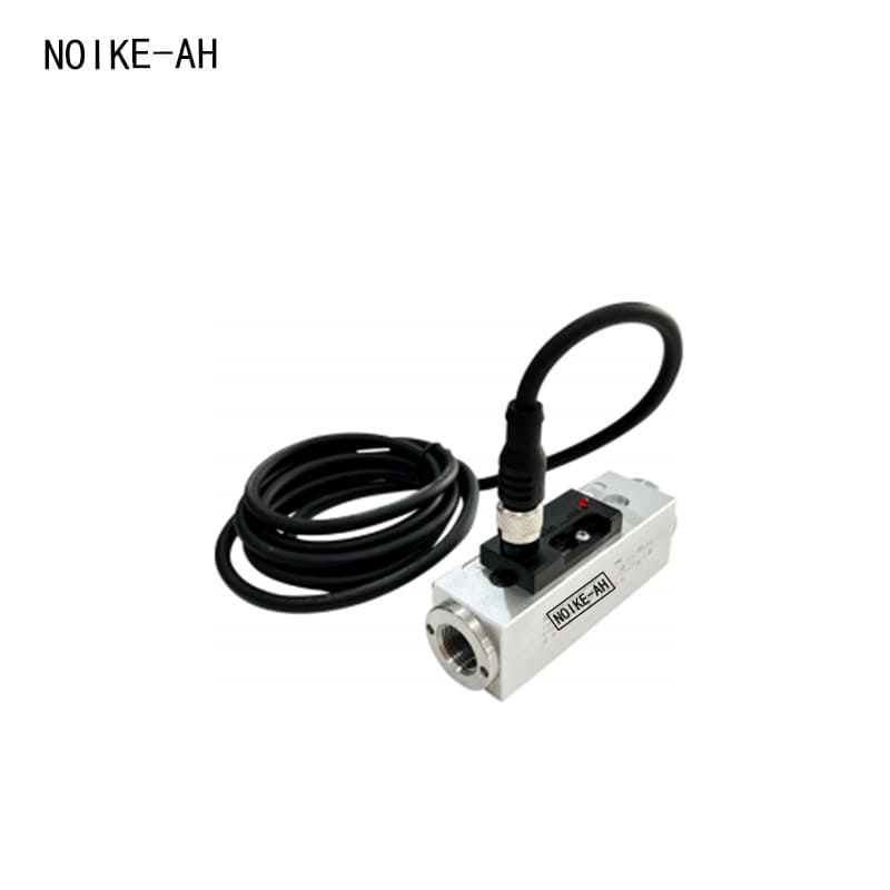
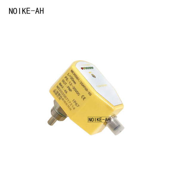
Piston Type Flow Switch NK200 Series
- Brand: NOIKE-AH
- Model:NK200 Series
Specification
Product Description
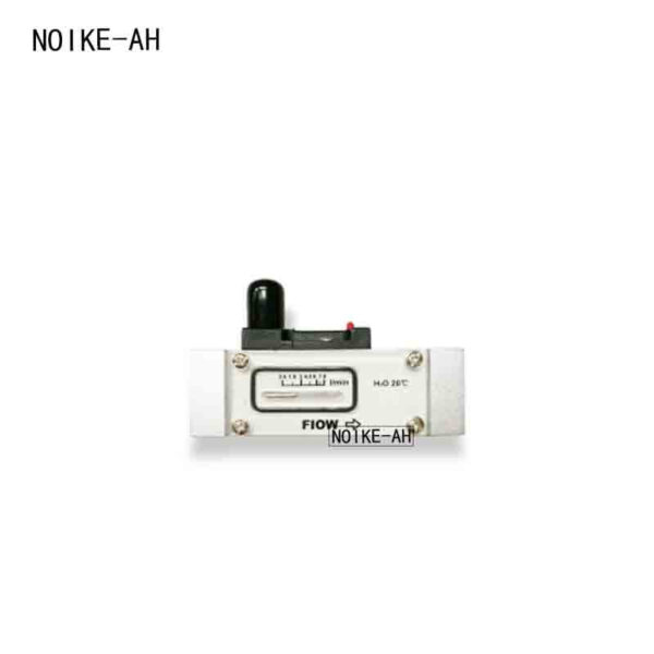
It is an in-line installed, mechanical flow switch, suitable for liquid or gas media. Sturdy plastic, aluminum or stainless steel enclosures are available. It features minimal pressure loss, good repeatability, anti-fouling capability, complete isolation between the mechanical part and the electronic part, and is suitable for small-flow economy applications. It is equipped with a switch setting scale, so users do not need to set it on site. It has an LED to display the switch status, and dual switch output is optional.
Principle and Structure
It is an in-line installed, mechanical flow switch, suitable for liquid or gas media. Sturdy plastic, aluminum or stainless steel enclosures are available. It has minimal pressure loss, good repeatability, anti-fouling capability, and complete isolation between the mechanical part and the electronic part, making it suitable for small-flow economy applications. It is equipped with a switch setting scale, so users do not need to set it on site. It has an LED to display the switch status, and dual switch output is optional.
Product Applications
It is gas-liquid dual-purpose, applicable to industrial automation/machinery equipment/air compression industry/refrigeration and air conditioning.
Water, oil
Technical Parameters
- Setting range: See parameter table
- DC power supply: LED displays the switch status; AC power supply: no LED display
- Accuracy: ±5% of full range
- Reed switch: capacity 24VDC/250VAC, 100mA
- Hysteresis: Depending on the switch point, minimum 0.5L/Min
- Switch setting scale: Calibrated under the conditions of water as the medium, temperature 20°C, and horizontal installation
- Pressure resistance: 50 bar (aluminum type), 100 bar (stainless steel type)
- Average pressure loss: 0.3 bar (at 25L/min)
- Installation position: Medium and temperature changes will have a slight impact on the switch
- Medium temperature: Maximum 90°C
- Wiring method: M12 5-core connector, Hausmann connector (optional)
- LED display: ◇
- Output: ◊
- Protection class: IP65
Anodized aluminum (stainless steel)
Parameter Table
| Model | Pressure (bar) | Maximum Flow L/min (Water) | Adjustable Range L/min (Water) | G (mm) | L mm | H mm | B mm | X mm | Weight (kg) |
|---|---|---|---|---|---|---|---|---|---|
| NK200-G14…010 | 50 | 40 | 0.6(0.1)-8(7) | G1/4 | 93 | 36 | 30 | 12 | 0.22 (0.53) |
| NK200-G38..L010 | 50 | 40 | 0.6(0.1)-8(7) | G3/8 | 93 | 36 | 30 | 15 | 0.20(0.51) |
| NK200-G12..L010 | 50 | 40 | 0.6(0.1)-(7) | G1/2 | 93 | 36 | 30 | 15 | 0.18(0.48) |
| NK200-G34…L010 | 50 | 40 | 0.6(0.1)-(7) | G3/4 | 105 | 36 | 35 | 15 | 0.23(0.65) |
| NK200-G1…L010 | 50 | 60 | 0.6(0.1)-8(7) | G1 | 105 | 36 | 40 | 15 | 0.32(0.82) |
| NK200-G14…L015 | 50 | 40 | 1(0.5)-15(13) | G1/4 | 93 | 36 | 30 | 12 | 0.22(0.53) |
| NK200-G38…L015 | 50 | 40 | 1(0.5)-15(13) | G3/8 | 93 | 36 | 30 | 15 | 0.20(0.51) |
| NK200-G12..L015 | 50 | – | 1(0.5)-15(13) | G1/2 | 93 | 36 | 30 | 15 | 0.18(0.48) |
| NK200-G34..L015 | 50 | 40 | 1(0.5)-1(13) | G3/4 | 105 | 36 | 35 | 15 | 0.23(0.65) |
| NK200-G1.L.015 | 50 | 60 | 1(0.5)-15(13) | G1 | 105 | 36 | 40 | 15 | 0.32(0.82) |
| NK200-G12..L028 | 50 | 40 | 2(0.8)-28(25) | G1/2 | 93 | 36 | 30 | 15 | 0.18(0.48) |
| NK200-G34..L028 | 50 | 60 | 2(0.8)-28(25) | G3/4 | 105 | 36 | 35 | 15 | 0.23(0.65) |
| NK200-G1…L028 | 50 | 40 | 2(0.8)-28(25) | G1 | 105 | 36 | 40 | 15 | 0.32(0.85) |
| NK200-G34…L070 | 50 | 100 | 27(21)-70(66) | G3/4 | 105 | 36 | 35 | 15 | 0.23(0.65) |
| NK200-G1…L070 | 50 | 100 | 27(21)-70(66) | G1 | 105 | 36 | 40 | 15 | 0.32(0.82) |
- 1/ The parameters in the above brackets are reset points, and those outside the brackets are action points; if it is lower limit alarm (monitoring too small flow), refer to the reset point parameters; if it is upper limit alarm (monitoring too large flow), refer to the reset point parameters.
- 2/ The above parameters are obtained by testing the switch vertically installed in a horizontal pipeline with 20°C water as the medium.
Wiring Diagram/Installation Direction
free
0 2 white
ὀ black
ὀ 4 1
ὀ 3
brown blue
Selection Table
| NK200 | 008 | G | D | L | 015 | C | 1 | W | Detailed Description |
|---|---|---|---|---|---|---|---|---|---|
| NK200 | NK200 series piston type flow switch | ||||||||
| G14 | Threaded interface G1/4 | ||||||||
| G38 | Threaded interface G3/8 | ||||||||
| G12 | Threaded interface G1/2 | ||||||||
| G34 | Threaded interface G3/4 | ||||||||
| G1 | Threaded interface G1 | ||||||||
| G | Internal thread (default) | ||||||||
| D | DC power supply 24V±20%DC | ||||||||
| A | AC power supply 230V±15%AC | ||||||||
| S | Plastic enclosure | ||||||||
| L | Anodized aluminum enclosure | ||||||||
| B | Stainless steel enclosure | ||||||||
| 008 | Setting range: 0.6-8L/min | ||||||||
| 015 | Setting range: 1-15L/min | ||||||||
| 028 | Setting range: 2-25L/min | ||||||||
| 070 | Setting range: 27-70L/min | ||||||||
| H | Hausmann connector | ||||||||
| Q | Aviation connector | ||||||||
| 1 | 1 switch point output (default) | ||||||||
| 2 | 2 switch point outputs | ||||||||
| W | External thread connection | ||||||||
| R | Hose connection |
- When placing an order, please specify the medium flow direction, medium type, pipe diameter and expected setting value. We can complete the setting for you before leaving the factory. Pipes larger than DN25 need to be ordered, and the required parameters and requirements should be provided when ordering.
Table of Contents
Talk With Us
- [email protected]
- +86 180 5512 0225
- +86(0551)-65501008
- Address: 206, Block B, No. 2 Tianda Road, High-tech Zone, Hefei City, Anhui Province, China
- We will respond to you within five minutes.
")