I. Mechanical Flow Switches
- Core Structure
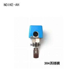
It mainly consists of three parts: target plate/paddle, spring, and microswitch. The target plate is installed vertically to the fluid flow direction inside the pipeline.
- Operating Principle
- When the fluid flow rate in the pipeline is below the preset value, the fluid impact force is small. The target plate maintains its initial position under the tension of the spring, and the microswitch stays in its initial on/off state.
- When the flow rate reaches the preset value, the fluid impact force exceeds the spring tension, pushing the target plate to displace. The displacement triggers the contact action of the microswitch, outputting a switching signal (e.g., turning on the alarm circuit, starting the pump unit).
- When the flow rate decreases, the impact force weakens, the spring pulls the target plate back to its original position, and the switching signal reverts to the initial state.
- Subtypes and Characteristics
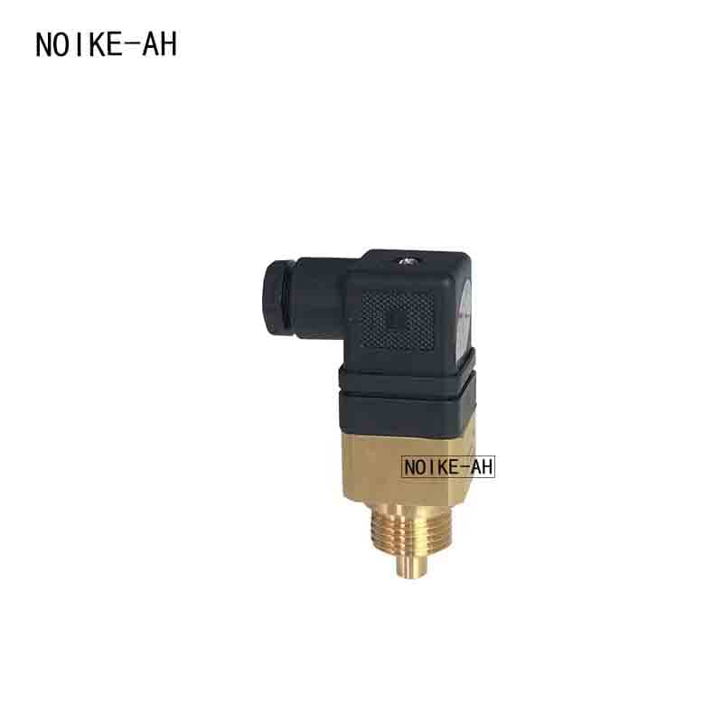
- Target-type flow switch: Suitable for liquids such as water and oil, it can withstand high-viscosity fluids with a small amount of impurities, and is commonly used in industrial circulating water systems.
- Piston-type flow switch: Triggers signals by fluid pushing the piston to move, featuring higher sensitivity, and is mostly used in small-diameter pipelines.
II. Thermal Conductivity Flow Switches
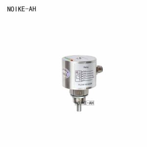
- Core Structure
It has two built-in temperature sensors: one is a heated sensor (with a built-in heating element, heated to a fixed value higher than the ambient temperature), and the other is a reference sensor (monitoring the actual temperature of the fluid). Both sensors are in direct contact with the fluid.
- Operating Principle
- After the sensors are powered on, the heated sensor is heated to a set temperature (e.g., 20°C higher than the reference sensor).
- When no fluid flows inside the pipeline (or the flow rate is extremely low), the heat of the heated sensor cannot be dissipated effectively, the temperature remains stable, and the temperature difference with the reference sensor is constant.
- When fluid flows, the fluid takes away the heat of the heated sensor. The higher the flow rate, the more heat is removed, causing the temperature of the heated sensor to drop and the temperature difference with the reference sensor to decrease.
- When the temperature difference drops to the preset threshold, the internal circuit determines that the flow rate meets the standard, and outputs a switching signal; when the flow rate decreases, the temperature difference rises, and the signal resets.
- Characteristics
Free from mechanical wear and long service life, it can monitor extremely low flow rates, but it is sensitive to the thermal conductivity of fluids (e.g., the thermal conductivity of air and water varies greatly, requiring targeted calibration).
III. Gas Flow Switches
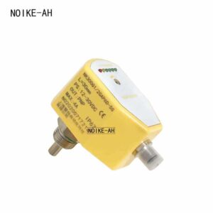
- Mainstream Type: Thermal Conductivity Gas Flow Switch
Its principle is consistent with that of ordinary thermal conductivity flow switches, but the heating power and temperature difference threshold of the sensors are optimized:
- The thermal conductivity of gas is much lower than that of liquid, so the heat of the heated sensor is more easily dissipated. Therefore, higher heating power is required to maintain the temperature difference.
- The internal circuit has higher sensitivity adjustment to the temperature difference change, which can capture the temperature difference change caused by the tiny gas flow rate.
- Auxiliary Type: Differential Pressure Gas Flow Switch
- It utilizes the differential pressure generated when gas flows through a throttling element (such as orifice plate, nozzle), where the differential pressure value is proportional to the square of the flow rate.
- When the differential pressure reaches the preset value, the differential pressure sensor triggers the switching signal, which is suitable for large-flow gas pipelines (e.g., compressed air, gas transmission).
- Characteristics
It has strong anti-interference ability and can avoid false triggering caused by gas pressure fluctuations. It is commonly used in gas leakage monitoring and compressed air system protection.
IV. Fire Protection Flow Switches
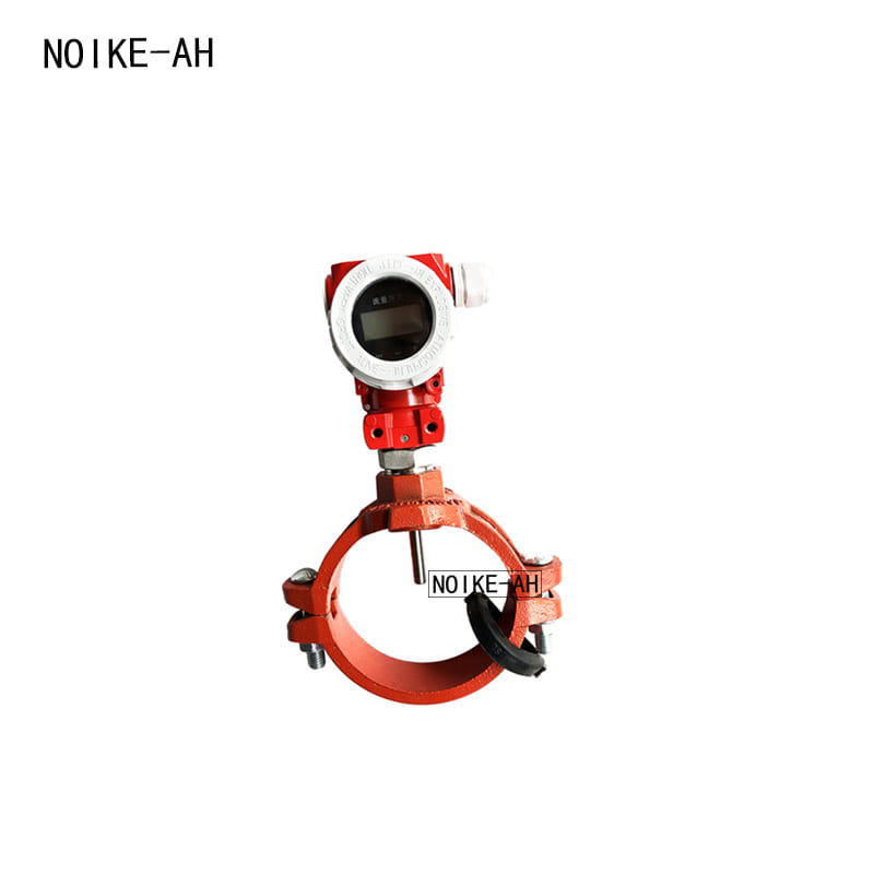
- Core Structure
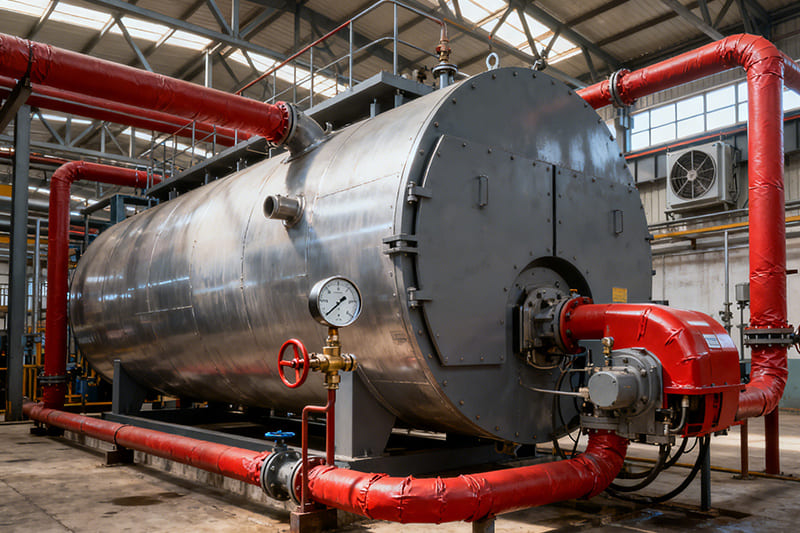
Taking the target-type fire protection flow switch as an example: it includes a large-diameter target plate, a waterproof microswitch, and a time-delay circuit, and is installed on the outlet side of the main fire protection pipeline.
- Operating Principle
- When a fire breaks out, fire hydrants or sprinkler heads are turned on, generating an instantaneous water flow in the fire protection pipe network, and the water flow impacts the target plate.
- Different from ordinary target-type switches, fire protection flow switches have a built-in time-delay circuit (usually adjustable from 5 to 30 seconds), which can avoid false triggering caused by water pressure fluctuations and water hammer effects in the pipeline.
- When the water flow continuously impacts the target plate and the duration reaches the time-delay threshold, the switch closes, sends a signal to the fire control cabinet, and automatically starts the main fire pump.
- Characteristics
With reliable operation and high waterproof rating, it must pass fire protection certification and is a key component of automatic fire protection water supply systems.
V. Electronic Flow Switches
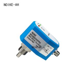
- Core Logic
The detection unit of an electronic flow switch can adopt different principles (such as target-type, thermal conductivity-type, ultrasonic-type, electromagnetic-type), but the signal processing unit is an electronic circuit, with the following characteristics:
- The detection unit collects physical quantities related to flow rate (such as target plate displacement, temperature difference, ultrasonic propagation time difference).
- The electronic circuit converts the physical quantities into electrical signals and compares them with preset thresholds.
- When the threshold is reached, a standard switching signal (such as PNP/NPN, normally open/normally closed) is output through transistors or relays.
- Common Subtypes
- Electronic target-type flow switch: On the basis of the traditional target-type, it uses a Hall sensor instead of a microswitch to detect target plate displacement, with higher accuracy and longer service life.
- Ultrasonic electronic flow switch: It calculates the flow rate by using the time difference of ultrasonic wave propagation in the fluid along the flow and against the flow. The non-contact measurement method is suitable for corrosive fluids.
- Characteristics
High precision, wide adjustable range, supporting digital signal output (such as 4~20mA, RS485), and easy integration with PLC and industrial control systems.
Comparison Table of Core Principles of Various Flow Switches
| Type | Core Principle | Key Advantages | Typical Application Scenarios |
|---|---|---|---|
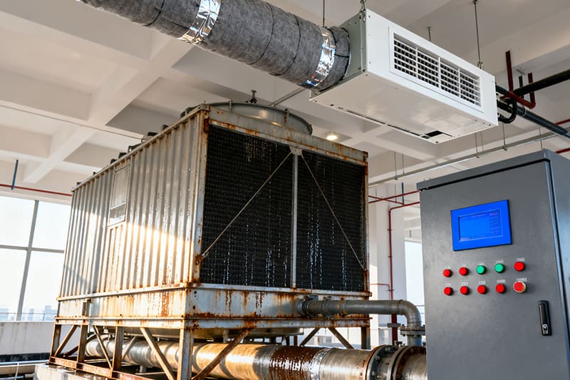
| Mechanical Flow Switch | Fluid impacts mechanical components to trigger signals | Anti-fouling, high pressure resistance, low cost | Industrial circulating water, cooling water systems |
| Thermal Conductivity Flow Switch | Temperature difference change caused by fluid heat transfer characteristics | No mechanical wear, high sensitivity | Pure water, chemical fluids, low-flow monitoring |
| Gas Flow Switch | Thermal conductivity/differential pressure principle adapted to gas media | Adapted to low-density gas, anti-pressure fluctuation | Compressed air, gas pipelines |
| Fire Protection Flow Switch | Target-type/differential pressure-type + time-delay circuit | Fire protection certified, anti-false triggering | Fire sprinkler, fire hydrant systems |
| Electronic Flow Switch | Electronic sensor + signal processing circuit | High precisio |