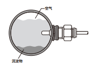
Principle/Structure
Based on the thermal principle, there are two resistors inside a closed probe, one of which is heated as the detection resistor and the other is not heated as the reference resistor. When the medium flows, the heat on the heating resistor is carried away, and the resistance value is changed. The difference between the two resistors is used as the basis for judging the flow rate.
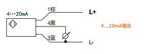
Wiring Diagram
Product Application
The explosion-proof mark of this product is ExdIICT6 Gb, which complies with GB3836. (1. GB3836.2, relevant standard requirements). Suitable for explosive hazardous environments in Zone 1 and Zone 2, Class IIA, IIB, and IIC, where flammable gases or vapors with ignition temperatures ranging from T1 to T6 form explosive mixtures with air.
*Note: When using this instrument, it is strictly prohibited to open the cover and operate it with electricity on
Technical Specifications
- Setting range: 1-300cm/s (water);
- 20-2000cm/s (air)
- Signal output: Analog quantity (4… 20mA)
- Power supply: 24V ± 20% DC
- Pressure resistance range: 100bar
- Medium temperature change: ≤ 4 ℃/s
- Electrical protection: reverse phase, short circuit, overload protection
- Protection level: IP65
- Medium temperature: -20 ° C to 90 ° C
Environmental temperature: -20 ° C to 80 ° C
Storage temperature: -20 ° C to 100 ° C - Material: Probe: Stainless Steel Shell: Cast Aluminum
Product Features
- No mechanical movable parts, corrosion-resistant, stable and reliable, long service life, long-term operation without special maintenance;
- The integrated design of the detection probe and signal processing circuit makes installation and use extremely convenient;
- Built in temperature compensation circuit minimizes the error caused by the medium and ambient temperature on the fluid flow rate;
- Optimal selection of new circuits with low heat generation, chip mounted components, and high reliability;
- This product has built-in analog output, only outputting 4… 20mA.
LED function and settings (switch type)
After installing the flow switch, allow the medium to flow at the low limit flow rate that needs to be monitored, adjust the lower limit knob to make the first green LED light up (4mA). Make the medium flow at the upper limit flow rate that needs to be detected, adjust the upper limit knob to turn on the fifth green light (20mA); Afterwards, the output will be proportional to the flow rate between the upper and lower limits, with 4mA corresponding to the lower limit flow rate and 20mA corresponding to the upper limit flow rate.
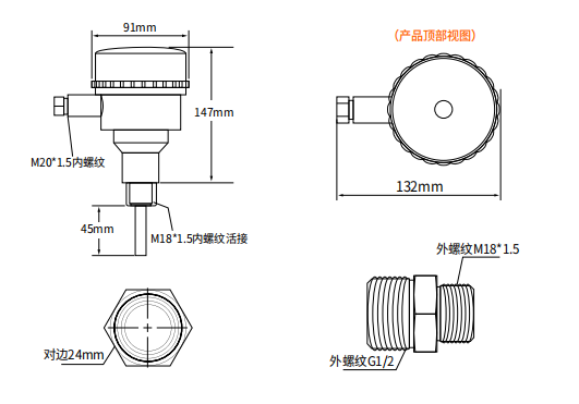
Dimensional drawing (mm)
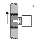
Installation direction

")