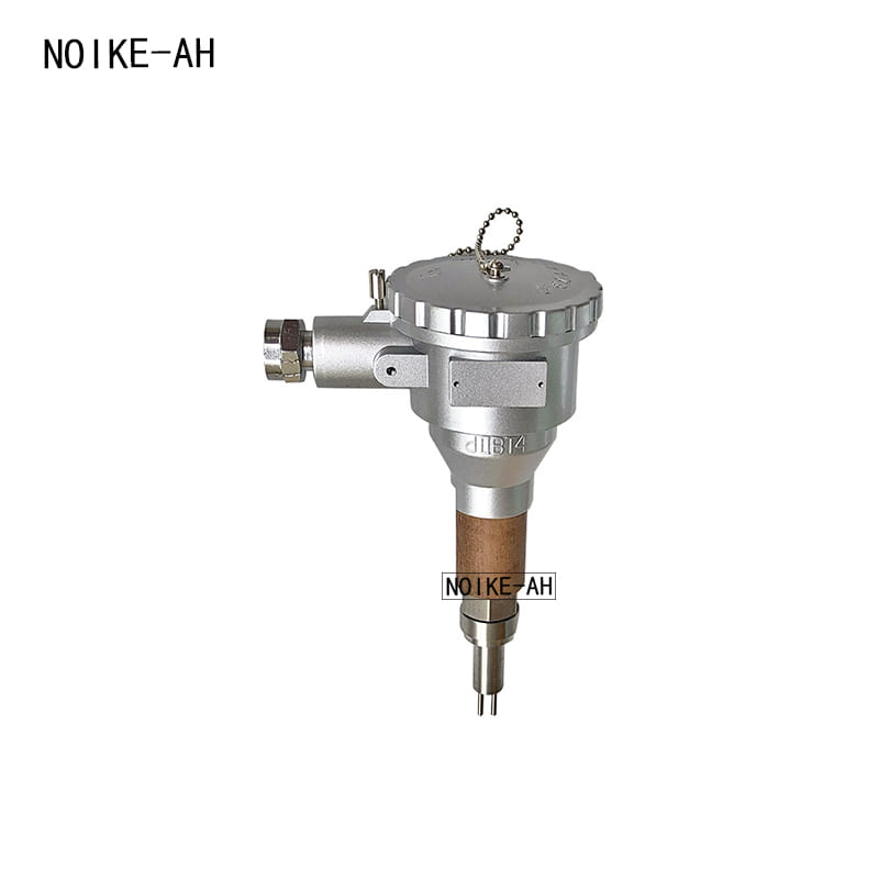
Working principle
The thermal mass flow sensor is designed based on the L · V · King heat exchange principle, with a flow sensor installed at the front end and two probes in contact with the medium. One measures the temperature of the medium, while the other measures and heats it up; The temperature difference between the two probes is maximum when there is no medium flow, and decreases when there is medium flow. The magnitude of temperature difference is related to the flow velocity of the medium.
The larger the flow velocity, the smaller the temperature difference, and the smaller the flow velocity, the larger the temperature difference; The maximum temperature difference occurs when there is no flow. It is also related to the thermal conductivity and humidity of the medium itself. When the flow rate is lower or higher than a certain set value, the relay is turned on or off to output a switch signal.
Product use
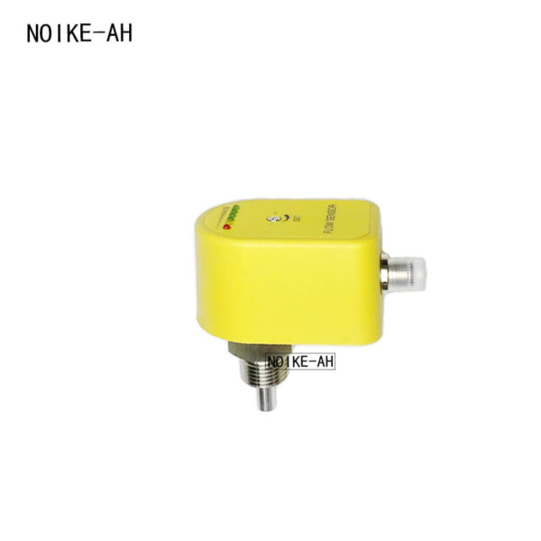
The NK33EX-90 explosion-proof flow sensor can be widely used for flow detection, alarm, and control in flammable and explosive places such as petroleum, chemical, power, metallurgy, etc.
Characteristics
- No mechanical movable parts, corrosion-resistant, stable and reliable, long service life, long-term operation without special maintenance.
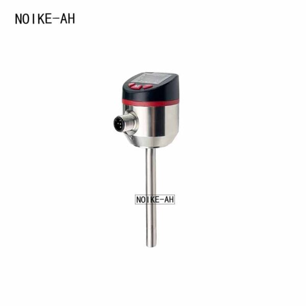
- The integrated design of the detection probe and signal processing circuit makes installation and use extremely convenient.
- The circuit is equipped with a temperature compensation circuit to minimize the error caused by the medium and ambient temperature on the fluid flow rate.
- Select a new type of circuit, using DC 24V ± 15% current ≤ 100mA power supply, with low circuit heat generation and chip installation of components, which improves reliability.
- The product adopts Exd Ⅱ CT6 explosion-proof design and can be used in Zone 1 or Zone 2 hazardous areas containing Class IIA or IIB explosive gases or vapors in factories.
Parameters:
- Power supply: DC24V ± 15%/100mA
- Medium temperature: -45~260 ℃ (high temperature type)
- Relative humidity: 5% to 95%
- Nominal pressure: 0-5Mpa
- Gas flow rate: 0-30m/s, liquid flow rate: 0-10m/s
- Protection level: IP65
- Explosion proof rating: Exd Ⅱ CT6 Gb
- Contact capacity: DC24V/3A
- Power on stability time: ≤ 3 minutes.
- Connecting cable: RVV4 × 1.0. Outer diameter: 10mm ± 0.5mm.
- Fixed methods: thread G1/2, NPT1/2, G3/4, NPT3/4, flange and other structures.
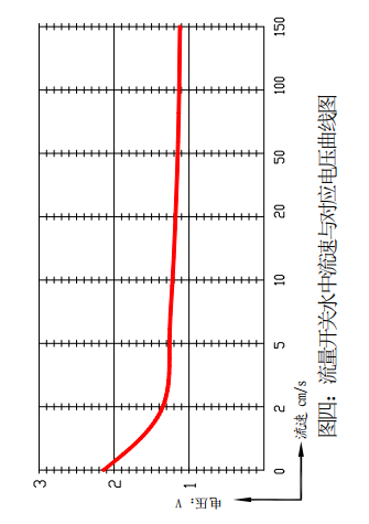
电压 Voltage
流速 Flow rate
Fig. 4: Flow Rate of Flow Switch in Water ~ Voltage Curve
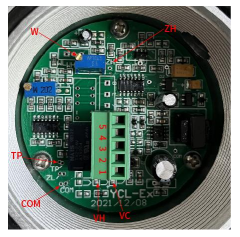
- Instrument debugging
Switch on 24V power source and carry out the instrument debugging after 3 minutes. “Com” refers to the common test point, “TP” the test point corresponding to the fluid (flow) and circuit voltage;
“W” potentiometer for threshold voltage regulation; “HZ” test point for voltage regulation of W potentiometer; “VC” power supply indication, and; “VH” relay action indication.
Fig. 4 shows the curve of measuring flow rate of this flow switch in tap water under 20℃ temperature VS TP1 voltage and can be used for reference when setting potentiometer is regulated by the flow switch.
Determine the set value for flow switch action (digital multimeter is required): divide the sum of voltage corresponding to com and TP at low speed of fluid and voltage corresponding to com and TP at high
图 四:流量开关水 中 流速与对应 电压 曲 线 图 流速 cm/s
V :压电speed by 2, i.e. threshold voltage of TP relay (through regulating W).
Set value of flow switch action: after determining the set value of flow switch action, regulate potentiometer (W) to make the voltage between com and ZH be equal to such value.
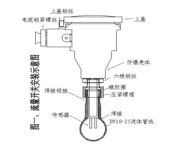
Fig. 1: Installation Instruction for Flow Switch
上盖锁丝 Lock screw of upper cover
电缆锁紧螺丝 Lock screw of cable
上盖 Upper cover
防爆壳体 Explosion-proof shell
六棱锁丝 Hexagonal lock screw
焊接短接 Welded shorting
橡胶圈 Rubber ring
压紧螺帽 Gland nut传感器 Sensor
焊接 Weld
DN10-25 流体管线 DN10-25 fluid pipeline
Installation method
On the horizontal (priority) direction of the high-temperature pipeline, if the length of the straight pipe section is ≥ 50cm, a circular hole with the same diameter as the welding short circuit should be opened in the middle and upper part of the straight pipe section. The short circuit attached to the flow switch should be welded to the circular hole, and then the flow switch with the sealing rubber ring installed should be rotated on the short circuit.
Suggestion: Insulation treatment should be carried out on high-temperature pipelines near the flow switch to reduce the heat conduction of high-temperature pipelines to the flow switch housing.
Wiring
Terminal 1: DC24+; 2:DC24-; 3: Normally closed contact;
4: Connecting common terminals; 5: Normally open contacts.
VC power indicator light, VH over limit indicator light.
When wiring, first introduce the cable into the flow switch housing,
Unplug the terminal connector, connect the cable and terminal connector according to the nature of the instrument output, insert the terminal connector into the female socket, and tighten the cable connector.